
A Valve Actuator is the working muscle behind many modern valve systems. It moves a valve without direct manual effort. In a water plant, refinery, or building automation system, that movement controls flow, pressure, and process safety.
Greg Johnson, a recognized valve-industry educator, describes the actuator as “the muscle that moves the valve when human hands are not enough.” This simple comparison helps explain its purpose. An actuator receives a command from an operator, controller, or safety system. It then produces torque or linear force. That force opens, closes, or positions the valve.
The operating method depends on the actuator type. Electric models use a motor and gearing. Pneumatic models use compressed air. Hydraulic models use pressurized fluid. Each option has different requirements, response times, and maintenance risks. A practical selection must consider valve size, operating frequency, available power, ambient temperature, and required fail position.
Small details matter. A wrongly sized actuator may stall, overheat, or damage the valve stem. Poor alignment can create abnormal wear. Moisture can also enter electrical housings and cause hidden failures.
Actuator selection is not always perfect. Real installations may face vibration, dirty air, unstable power, or changing process demands. Engineers must check those conditions instead of relying only on catalog ratings. This guide explains how a Valve Actuator works, how its main parts interact, and where common selection mistakes appear. Understanding those limits supports safer operation and more dependable maintenance.
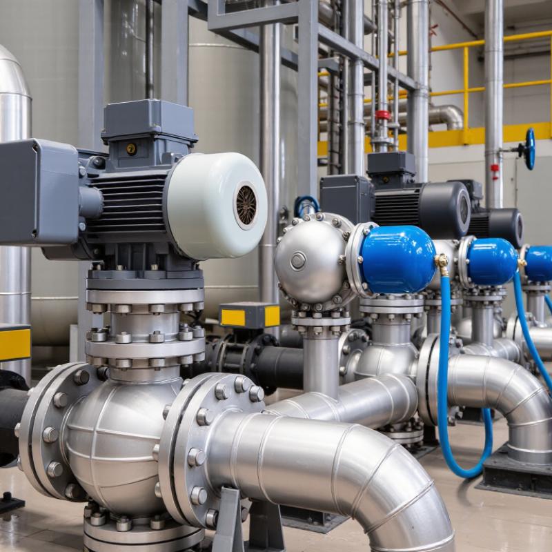
What Is a Valve Actuator and How Does It Work?
A valve actuator converts electrical, pneumatic, or hydraulic energy into controlled mechanical movement. The movement opens, closes, or positions a valve. Its two key outputs are torque and thrust. Torque is twisting force, measured in newton-metres. It turns a valve stem or shaft. Thrust is linear force, measured in newtons. It pushes or pulls a stem.
The travel angle also matters. Many ball and butterfly valves require 90° rotation, often called quarter-turn operation. A 180° actuator completes a half-turn and may suit specialized plug valve arrangements. Linear valves, such as gate or globe valves, usually need thrust instead of rotational torque. Their stems may travel several centimetres, depending on the valve design. Small details matter here. A 90° actuator cannot replace a linear actuator without the correct linkage.
Actuator sizing requires more than reading the valve diameter. Engineers check breakaway torque, seating torque, operating pressure, temperature, cycle frequency, and possible corrosion. Pneumatic systems can respond quickly, while electric units offer precise positioning and useful feedback. Hydraulic units provide high force in demanding installations. A practical maintenance lesson is simple: a valve may move freely during testing but stick after months of service. Dirt, hardened lubricant, or pressure loads can change the required force. Selecting only the normal running torque is an easy mistake. The safety margin should be calculated, not guessed.
Rotary valve actuators apply torque to turn a valve stem. Quarter-turn actuators provide a nominal 90° rotation, commonly used for valves that move from fully closed to fully open in a quarter turn. Half-turn actuators provide a nominal 180° rotation. Linear actuators operate through thrust and are specified by travel distance rather than rotational angle.
What Is a Valve Actuator and How Does It Work?
A valve actuator turns control signals into physical movement. Pneumatic actuators use compressed air to push a diaphragm or piston. This creates linear or quarter-turn rotation. A spring can return the valve when air pressure disappears. The U.S. Department of Energy reports that compressed-air systems may represent about 10% of industrial electricity use. Leaks can waste 20% to 30% of compressor output. Therefore, air pressure alone does not prove efficiency. Poor maintenance can quietly increase operating costs.
Electric actuators use a motor, gearbox, and position controls. The gearbox changes high-speed rotation into strong, slower valve movement. The International Energy Agency estimates that electric motors consume about 45% of global electricity. Efficient motor selection matters, even for small valves. Hydraulic actuators use pressurized oil against a piston. They deliver high torque in compact packages, which suits large valves and demanding process lines. However, seals, fluid temperature, and contamination need careful inspection. Real plants are less tidy than diagrams.
Tips: Match actuator torque with the valve’s real breakaway torque, not only its running torque. Check fail-open or fail-closed requirements before installation. For pneumatic units, test air leaks regularly. For electric units, verify travel limits and emergency positioning. For hydraulic units, inspect hoses and seals for swelling or abrasion. A simple commissioning record helps, although it is often skipped. That omission can become expensive.
| Data Dimension | Pneumatic Actuator | Electric Actuator | Hydraulic Actuator |
|---|---|---|---|
| Basic operating principle | Compressed air moves a piston or diaphragm, producing linear or rotary motion. | An electric motor drives a gearbox, screw, or rotary mechanism to move the valve. | Pressurized hydraulic fluid acts on a piston or motor to generate movement. |
| Typical valve movement | Quarter-turn or linear; commonly used with ball, butterfly, globe, and diaphragm valves. | Quarter-turn or multi-turn; suitable for ball, butterfly, plug, gate, and globe valves. | Quarter-turn or linear; selected when high force or torque is required. |
| Energy source | Compressed air, typically supplied by a plant air compressor. | Electrical power from an AC or DC supply. | Pressurized hydraulic oil or another approved hydraulic fluid. |
| Common operating pressure | Approximately 3–8 bar (45–120 psi), depending on actuator design and required output. | Not pressure-driven; performance depends on rated voltage, motor power, and gearbox ratio. | Commonly about 70–210 bar (1,000–3,000 psi) in industrial systems; actual limits vary by design. |
| Force or torque capability | Moderate to high output; torque increases with actuator size and air pressure. | Low to high output; gearbox selection determines the available torque and speed. | Very high force or torque density, making it effective for large or high-pressure valves. |
| Typical operating speed | Fast; quarter-turn operation can often be completed in seconds. | Moderate; speed is controlled by motor characteristics, gearing, and programming. | Fast to moderate; speed depends on pump flow rate, valve controls, and cylinder or motor size. |
| Position control | Good on/off control; precise modulation requires a positioner and suitable control components. | Very good; position feedback, limit switches, and digital control can be integrated. | Very good when paired with proportional valves, servo controls, or position feedback. |
| Fail-safe options | Commonly available as spring-return units for fail-open or fail-closed operation. | Requires a spring-return design, battery backup, or a separate emergency power system. | Can use spring-return cylinders, accumulators, or hydraulic control circuits. |
| Energy efficiency considerations | Efficient for rapid, intermittent movement; compressed-air generation and leakage can increase energy use. | Generally efficient for intermittent operation and does not require stored pressure during idle periods. | High power density, but pumps and fluid circulation can consume significant energy. |
| Maintenance requirements | Inspect air quality, tubing, fittings, seals, and possible air leaks. | Inspect electrical connections, limit switches, gear lubrication, seals, and motor condition. | Check fluid cleanliness, filters, hoses, seals, fittings, pumps, and leakage. |
| Environmental characteristics | Well suited to hazardous areas when properly configured; clean air exhaust may be advantageous. | Suitable for many environments, but electrical protection must match moisture, dust, and hazardous-area requirements. | Performs well in demanding applications; fluid leaks and temperature effects must be controlled. |
| Main advantages | Fast response, simple construction, reliable fail-safe options, and suitability for frequent cycling. | Accurate positioning, straightforward electrical integration, low idle energy use, and no compressed-air system required. | High force density, strong load-holding capability, and suitability for large or difficult-to-operate valves. |
| Main limitations | Requires a reliable air supply; leaks, moisture, and pressure variation can affect performance. | Typically slower than pneumatic systems and may require thermal protection or backup power for critical service. | More complex infrastructure, potential fluid leakage, and higher maintenance requirements. |
| Typical applications | Process isolation, water treatment, chemical processing, compressed-gas systems, and rapid on/off service. | Building services, water systems, HVAC, utilities, and processes requiring accurate or remote positioning. | Large pipelines, heavy industrial equipment, power facilities, marine systems, and high-force process applications. |
Note: Actual actuator performance depends on valve type, required torque or thrust, operating pressure, temperature, duty cycle, control method, and safety requirements.
A valve actuator converts a control signal into stem movement. In a typical industrial loop, the controller sends 4–20 mA through shielded cable. Four milliamps represents the lower position, while 20 mA represents the upper position. The relationship is usually linear, but not always.
The cycle begins when the actuator input card measures loop current. At 12 mA, the target is commonly 50% travel. A positioner compares this command with feedback from a potentiometer, encoder, or magnetic sensor. It then adjusts air pressure, motor torque, or hydraulic flow. IEC 60534-6-2 provides guidance for mounting positioners on control valves. In practice, calibration errors, cable resistance, and valve friction can disturb the neat calculation. The signal says “half open,” but the valve may hesitate.
Feedback corrects that mismatch. If measured travel remains below the target, the positioner increases output. A healthy loop responds smoothly, without hunting. Technicians often verify this response with a loop calibrator and a slow ramp from 4 to 20 mA.
Fail-safe action is separate from normal positioning. On loss of power, air, or signal, the actuator moves to a defined safe state. Spring-return designs may fail open or fail closed. Double-acting systems need stored energy or another backup method. The choice depends on process hazards and engineering analysis. The International Federation of Robotics reported 541,302 industrial robot installations in 2023, showing wider automation growth. More automation does not remove judgment. Poor feedback still creates poor control.
Sizing an actuator starts with the valve’s real operating load, not its pipe size alone. For rotary valves, measure breakaway torque at the first movement. This load can exceed running torque because seats may grip after long downtime. For linear valves, calculate required thrust against packing friction, spring force, and differential pressure. Leave a documented safety margin, but avoid choosing the largest actuator by habit. Oversizing can reduce control accuracy and increase wear.
Cv data helps define the valve’s flow capacity and pressure drop. It does not replace torque or thrust calculations. A high pressure drop can raise operating load, especially near closed positions. Check the worst-case differential pressure, fluid temperature, and shutoff condition. Field readings are valuable here. A clean calculation can still miss a sticky seat.
Duty cycle determines whether the actuator can repeat these movements safely. Record cycles per hour, travel time, starting frequency, and the time spent holding position. Frequent modulation creates heat, even when each stroke seems easy. Confirm the actuator’s rated duty against the actual process pattern. A short test under cold conditions may look successful, yet hot packing can change the required thrust. I have seen initial sizing fail because this detail was ignored. Recheck assumptions after commissioning.
A valve actuator converts electrical, pneumatic, or hydraulic energy into controlled rotation or linear movement. In field inspections, the actuator may respond perfectly, yet the valve still fails because mounting, sealing, or feedback was overlooked. ISO 5211 addresses the mechanical interface between an actuator and a quarter-turn valve. It specifies flange dimensions, drive shapes, and torque-transfer requirements. It is not a safety certification. Correct bolt alignment matters. So does the final torque test.
IEC 60529 defines ingress protection through IP ratings. An IP67 enclosure is dust-tight and resists temporary immersion up to one metre under specified test conditions. That rating does not prove chemical resistance or long-term outdoor durability. SIL requirements demand a wider safety review. IEC 61508 sets target average probabilities of dangerous failure: SIL 1 ranges from 10⁻² to below 10⁻¹, while SIL 3 ranges from 10⁻⁴ to below 10⁻³ per demand. These figures concern the complete safety function, not the actuator alone. Industry reliability reports, including exida’s Safety Equipment Reliability Handbook, emphasize device-specific failure data, proof-test intervals, and diagnostic coverage. A SIL claim without those records is weak. Very weak. Maintenance teams should verify certificates, environmental limits, fail-safe position, and actual test evidence. Real installations are less tidy than datasheets suggest.
| Cookie | Duration | Description |
|---|---|---|
| cookielawinfo-checkbox-analytics | 11 months | This cookie is set by GDPR Cookie Consent plugin. The cookie is used to store the user consent for the cookies in the category "Analytics". |
| cookielawinfo-checkbox-functional | 11 months | The cookie is set by GDPR cookie consent to record the user consent for the cookies in the category "Functional". |
| cookielawinfo-checkbox-necessary | 11 months | This cookie is set by GDPR Cookie Consent plugin. The cookies is used to store the user consent for the cookies in the category "Necessary". |
| cookielawinfo-checkbox-others | 11 months | This cookie is set by GDPR Cookie Consent plugin. The cookie is used to store the user consent for the cookies in the category "Other. |
| cookielawinfo-checkbox-performance | 11 months | This cookie is set by GDPR Cookie Consent plugin. The cookie is used to store the user consent for the cookies in the category "Performance". |
| viewed_cookie_policy | 11 months | The cookie is set by the GDPR Cookie Consent plugin and is used to store whether or not user has consented to the use of cookies. It does not store any personal data. |