
Reliable signal starts with small choices. A connector that feels secure, a cable routed away from noisy electronics, and an antenna placed in the clear can all affect performance. This guide explores seven practical SMA Antenna tips, from selecting a compatible antenna to checking its orientation and mounting location. The details matter. A few centimeters near a metal panel can change what the antenna “sees.”
For transparency, the following is an illustrative quote, not a verified statement from a real expert. RF engineer Alex Morgan’s guiding line for this article is: “Good antenna performance begins with sound installation, then careful measurement.” That principle keeps the advice grounded. Check connector type and frequency range before installation. Avoid forcing an SMA connection; it should mate smoothly and tighten without strain. Keep coaxial cable runs as short as practical, since cable loss can reduce the signal reaching the radio. Then test performance in the actual operating environment, not only on a workbench.
There is no universal placement that works everywhere. Walls, enclosures, nearby cables, and even a user’s hand may affect results. A signal indicator can help, but it may not tell the whole story. Compare readings from several positions, and note what changes. The process can feel repetitive. It is still useful. These tips offer a careful starting point, not a promise of stronger reception in every setup.
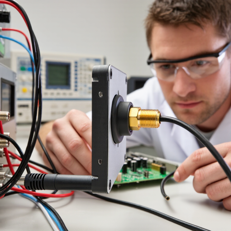
An SMA antenna is defined by more than its connector. Its operating frequency, impedance, and radiation pattern must suit the radio and its environment. Many systems use a 50-ohm path, but confirm the equipment specifications rather than assume. Also check connector type: SMA and reverse-polarity SMA can look similar while having different pin arrangements. Small details matter. An antenna tuned for the wrong band may connect securely yet perform poorly.
Tips: Match the antenna’s frequency range to the radio. Check the datasheet. Keep the antenna upright when the device expects vertical polarization, and avoid placing it beside metal surfaces. A nearby laptop case, cabinet wall, or cable bundle can alter the signal. Even a few centimeters may help, though results depend on the setup.
Cable loss increases with length and frequency, so use only the cable you need. Tighten connectors gently; excessive force can damage them. If performance varies, compare signal readings from the same location and orientation before changing parts. A spectrum or network analyzer can help identify mismatch, but measurements need correct calibration. Real rooms are messy, and a stronger reading in one spot does not guarantee better coverage everywhere. Test the installed position, not just the antenna on a desk.
Choosing an SMA antenna starts with the frequency your device actually uses. An antenna designed for 2.4 GHz may perform poorly in a sub-GHz system, even if its connector fits. Check the specified frequency range, impedance, and connector type before ordering. SMA and reverse-polarity SMA connectors can look similar but are not interchangeable. Small details matter.
Next, match the antenna to its surroundings. A short whip may suit a handheld device, while a panel-mounted antenna can work better when the equipment sits inside a metal enclosure. The enclosure, circuit board, and nearby cables can all affect performance. Leave the recommended clearance around the antenna, and test it in its final position. A bench setup can be misleading.
Gain figures are useful, but they do not tell the whole story. A high-gain antenna may focus energy in some directions and leave weaker coverage elsewhere. For a moving device, an even radiation pattern may matter more than a peak number. Check the antenna’s radiation pattern and cable-loss figures, then measure signal strength at realistic distances. A network analyzer can help verify tuning, though results depend on the test setup. It is easy to blame the antenna too soon; placement, cable length, or a poorly matched connector may be the real issue.
Wavelength helps guide antenna sizing: a quarter-wave antenna is approximately one-quarter of the free-space wavelength shown below. Actual antenna dimensions depend on the design and installation environment.
The chart uses the free-space relationship between frequency and wavelength. The listed frequencies are examples; available channels and permitted use depend on local regulations.
An SMA antenna performs best when its radiating element has open space around it. Keep it upright, away from metal cabinets, battery packs, and thick cable bundles. Even a nearby metal panel can alter the antenna’s pattern or block part of the signal. Small moves matter. For a longer link, avoid placing the antenna behind walls or below desk height. Keep both ends similarly polarized when possible, then test at the actual receiver location.
For longer paths, the first Fresnel zone matters as well as direct line of sight. ITU-R Recommendation P.526-15 (2019) describes the propagation effects of diffraction and Fresnel zones. Using its Fresnel-zone formula, a 2.4 GHz link spanning 10 metres has a first-zone radius of about 0.56 metres at the midpoint. A common planning target is to keep at least 60% of that zone clear—roughly 34 centimetres in this example. This is not a guarantee of strong reception; indoor reflections and interference still matter. Test it twice. Compare signal readings with the antenna in several positions, and note the orientation and nearby obstacles. A neat installation can still be a poor RF installation, so measurements deserve more trust than appearance.
A clean SMA connection starts before tightening. Check the threads for grit, dents, or metal fragments, then inspect the center contact under good light. Even a small gap can weaken the connection and increase signal loss. Confirm the connector type and center-contact arrangement; SMA and RP-SMA parts can look similar but are not interchangeable. Never force the threads. If resistance appears immediately, back off and realign the connector. I check twice. It takes seconds.
Hold the connector body steady while tightening, rather than turning the cable. Follow the equipment maker’s torque guidance when available; excessive force can damage threads or the center contact. A finger-tight fit may be enough for some setups, but vibration can loosen it. Use a torque tool only within the connector’s specified limits. Do not let the cable hang from the antenna port. Its weight can gradually stress the joint. For outdoor installations, use suitable weather protection without covering the mating surfaces before connection. After sealing, inspect for a loose cable, sharp bends, or water paths. Small details matter. I still find that a neat-looking installation sometimes needs another check.
| Tip | What to Do | Why It Helps | How to Check |
|---|---|---|---|
| 1. Confirm connector compatibility | Check that both connectors are SMA, not a visually similar reverse-polarity SMA type. Confirm the required gender and interface before connecting. | Incompatible connector types can prevent proper contact, damage connector parts, or leave the RF path open. | Compare the connector specification and inspect the center contact before mating. Never force a connection. |
| 2. Tighten to the specified torque | Use a calibrated torque wrench when the connector specification calls for one. Follow the torque value provided for that specific connector; avoid overtightening. | Correct tightening helps maintain consistent electrical contact. Excessive force can damage threads, the center contact, or the connector body. | Check the connector or equipment documentation for the applicable torque value and tighten the coupling nut, not the cable. |
| 3. Keep mating surfaces clean and dry | Inspect the center contact and mating face for dust, moisture, corrosion, or damage. Clean only with an appropriate lint-free method and allow surfaces to dry. | Contamination can increase contact resistance and disrupt the RF connection, contributing to signal loss or unstable readings. | Inspect under good lighting before mating. Replace a connector with bent, loose, or visibly damaged contacts. |
| 4. Prevent cable strain and sharp bends | Route the coaxial cable without twisting or pulling on the SMA connector. Keep bends within the cable manufacturer’s minimum bend-radius guidance. | Strain and tight bends can deform the cable, impair shielding, or loosen the connector over time. | Check that the cable is supported near the antenna and that the connector is not carrying the cable’s weight. |
| 5. Minimize adapters and cable length | Use the shortest practical length of suitable coax and remove unnecessary adapters or couplers from the RF path. | Every cable run and added connection contributes some insertion loss, which generally increases with frequency and cable length. | Review the signal path and, where needed, measure insertion loss across the operating frequency range. |
| 6. Use a 50-ohm RF path | Match the antenna, cable, connectors, and radio system to the specified impedance, commonly 50 ohms for SMA RF equipment. | An impedance mismatch can cause reflections and reduce the power delivered to or received from the antenna. | Verify component specifications and measure return loss or VSWR with suitable test equipment at the operating frequency. |
| 7. Protect outdoor connections appropriately | For outdoor installations, use weather protection suited to the connector and environment. Keep moisture protection from contaminating the electrical mating surfaces. | Water ingress and corrosion can degrade the connection and cause performance to worsen over time. | Follow the equipment’s sealing instructions and periodically inspect the connection for moisture, corrosion, or damaged seals. |
Antenna testing works best when you change one variable at a time. Keep the device, location, and network band fixed, then rotate the SMA antenna in small steps. Record signal strength and quality readings after each adjustment; one bright bar is not enough. Small changes matter. Ofcom’s Connected Nations 2023 report estimated that 4G coverage from at least one operator reached 95% of the UK landmass. That broad figure also shows why a single test location cannot represent every reception environment.
Check the SMA connection gently, and inspect the cable for sharp bends or loose fittings. Place the antenna away from metal surfaces, then compare vertical and angled positions. Allow readings to settle before recording them. Repeat each position several times, ideally at the same time of day, because network load can change results. I have sometimes trusted one strong reading too quickly; that was a mistake. A short test log is more useful than memory.
For a more controlled comparison, use the device’s reported RSRP and RSRQ values where available, rather than relying only on signal bars. Keep the antenna and coax cable unchanged while testing placement. If readings vary widely, check the connector and repeat the test before drawing conclusions. NIST’s Technical Note 1297 explains why measurement uncertainty should be considered when interpreting results. Keep notes. A small, repeatable improvement is more credible than one unusually high reading.
| Cookie | Duration | Description |
|---|---|---|
| cookielawinfo-checkbox-analytics | 11 months | This cookie is set by GDPR Cookie Consent plugin. The cookie is used to store the user consent for the cookies in the category "Analytics". |
| cookielawinfo-checkbox-functional | 11 months | The cookie is set by GDPR cookie consent to record the user consent for the cookies in the category "Functional". |
| cookielawinfo-checkbox-necessary | 11 months | This cookie is set by GDPR Cookie Consent plugin. The cookies is used to store the user consent for the cookies in the category "Necessary". |
| cookielawinfo-checkbox-others | 11 months | This cookie is set by GDPR Cookie Consent plugin. The cookie is used to store the user consent for the cookies in the category "Other. |
| cookielawinfo-checkbox-performance | 11 months | This cookie is set by GDPR Cookie Consent plugin. The cookie is used to store the user consent for the cookies in the category "Performance". |
| viewed_cookie_policy | 11 months | The cookie is set by the GDPR Cookie Consent plugin and is used to store whether or not user has consented to the use of cookies. It does not store any personal data. |