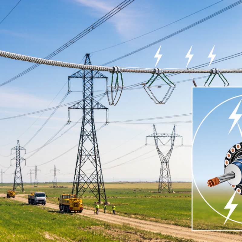
| Primary Function | Combines an overhead ground wire with optical-fiber communication capability. | Provides lightning shielding and a protected communications path on the same transmission-line structure. |
| Full Name | Optical Ground Wire. | Describes the cable’s dual role as both a grounding conductor and a fiber-optic cable. |
| Typical Installation Position | Installed at the top of transmission towers, above the phase conductors. | The elevated position helps intercept lightning and maintain a shielding angle over energized conductors. |
| Optical Fiber Count | Common designs contain approximately 12 to 48 fibers; higher-count designs are also available. | Fiber capacity can support protection signaling, supervisory control, voice, data, and utility telecommunications. |
| Fiber Type | Usually single-mode fiber compliant with applicable telecommunications standards. | Single-mode fiber supports long-distance, high-bandwidth transmission with low attenuation. |
| Typical Outside Diameter | Approximately 8 to 20 mm, depending on the electrical and mechanical design. | Diameter affects weight, wind loading, ice loading, fittings, and compatibility with existing towers. |
| Typical Cable Mass | Approximately 300 to 1,500 kg/km, depending on diameter, materials, and strength requirements. | The mass must be included in tower loading calculations and sag-tension analysis. |
| Rated Tensile Strength | Common designs range from roughly 40 to 150 kN, with project-specific values outside this range. | Strength must withstand installation loads, wind, ice, vibration, and long-term mechanical stress. |
| Short-Circuit Current Capability | Often designed for approximately 10 to 40 kA for 0.5 to 1 second, subject to the selected conductor design. | The cable must safely carry fault current until protective devices clear the fault. |
| Electrical Resistance | Common designs are approximately 0.2 to 1.0 ohm/km at 20°C. | Lower resistance helps reduce voltage rise and heating during fault-current events. |
| Optical Attenuation | For many single-mode fibers, approximately 0.22 to 0.35 dB/km at common operating wavelengths. | Lower attenuation increases communication distance and available optical power margin. |
| Operating Temperature | Typically rated for approximately -40°C to +70°C, with some designs supporting higher conductor temperatures. | Temperature limits influence sag, optical performance, material selection, and emergency operating conditions. |
| Lightning and Fault Protection | The metallic layers provide a conductive path for lightning current and phase-to-ground fault current. | Helps protect phase conductors, towers, insulation, and connected equipment when properly grounded. |
| Communication Applications | Teleprotection, SCADA, substation communications, operational voice, monitoring, and network data. | Enables fast, reliable information exchange for grid control, fault detection, and system coordination. |
| Main Advantages | Dual functionality, electromagnetic immunity of optical fibers, high bandwidth, and efficient use of tower space. | Reduces the need for separate grounding and communication infrastructure along the line route. |
| Key Design Considerations | Tower geometry, span length, wind and ice conditions, fault current, sag, vibration, fiber capacity, and installation method. | Correct design ensures mechanical reliability, electrical safety, optical performance, and compatibility with the transmission corridor. |
| Common Reference Standards | IEC 60794-4, IEEE 1138, IEC 61089, and applicable national utility specifications. | Standards define or guide requirements for optical performance, mechanical behavior, electrical properties, testing, and installation. |